The Heater
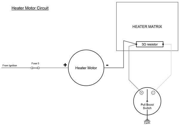
The 'Pull-Boost' switch connects the earth to either (H) - the High/Fast or Boost speed, or (L) - the Low/Slow speed, when the current flows through the resistor. The cables on my particular GT6 are as follows:
| Cables | |
| Green | From Fuse to Heater Motor (+ve) |
| Slate | Heater Motor (-ve) to Resistor in Matrix |
| Green/Yellow | Resistor in Matrix to Pull/Boost control (Low speed) - passing through resistor |
| Green/Slate | Resistor in Matrix to Pull/Boost control (High speed) - bypassing resistor |
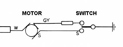
In the official Workshop Manual circuit diagram for the MK2 GT6 the Green/Slate cable has no colour specified, and the live wire to the motor is white, not green!
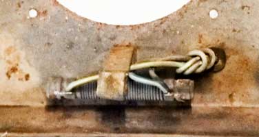
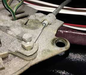
The 3Ω resistor can be seen below:
The Heater Controls
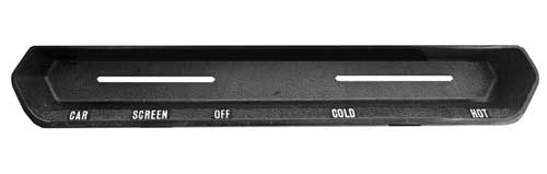
The heater is controlled by two knobs in the facia, above. The right knob operates a valve on the rear of the engine via a cable. The left knob labelled "Pull Boost" controls the direction of the air flow, and also the motor speed. Looking inside, this device is quite clever in how it controls two functions with the same knob, see below:
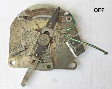
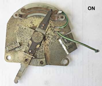
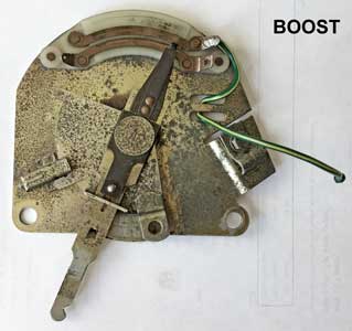
The position of the lever controls the direction of the flow by a short cable (not connected, see below) to the heater matrix flap. The curved contacts at the top ensure that contact is made irrespective of the position of the lever - at present in the "CAR" position.
![]()