Part of the renovation of my GT6 included the perhaps deluded decision to replace all the 1970s wiring. Rather than buy an off-the-shelf wiring loom, I decided to upgrade the whole system to more fuses than the original three (see below) and in the absence of any pre-designed system in any of the books I have acquired over the years, or on the internet, I had to design my own.
One advantage of doing it this way is that I decided on the specifications. These were as follows:
- An uprated 60 amp Alternator with uprated cables.
- Rewired to the highest level with modern thin wall single core PVC cable.
- Lights separately earthed (to eliminate earthing problems using the bodywork).
- Daytime Running Lights fitted in the sidelight part of the headlamps so I can be seen!
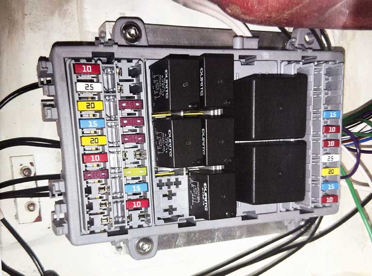
- A modular blade type fuse box (with relays & electronic indicator/hazard units, with OE clicker).
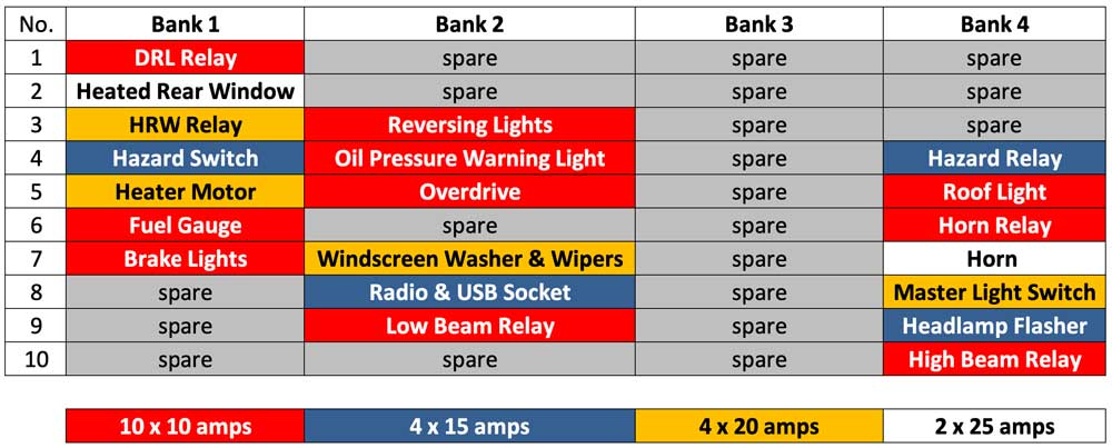
- Five relays for (1)Headlamp Low Beam, (2) Headlamp High Beam, (3) Daytime Running Lights, (4) Horn and (5) Heated Rear Windows.
- At least 20 fuses.
- For simplicity each circuits would be constructed separately and tested before embarking on the next. All the cables would then be wrapped in Easy Loom™.
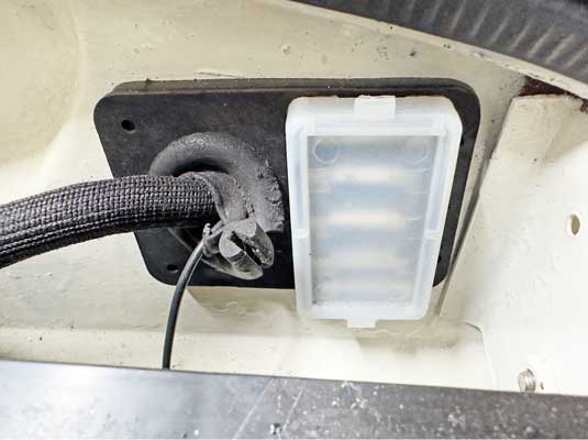
The original fusebox to be retained complete with fuses, but non-functioning to retain original appearance – cables to pass through.
Cables to be connected with traditional bullet connectors. To see the tools I used visit “Tools” or click here.
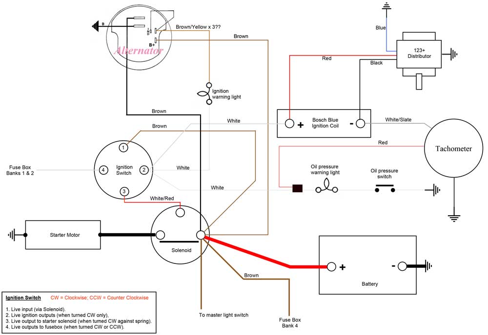
A spreadsheet was used to track each of 104 individual wires and its colour code, together with detailed wiring diagrams for each of 13 circuits.
These circuits were designed using the ‘Original Wiring Diagram – right hand steer” as a basis, if appropriate. Then loom diagrams were drawn up using the circuits as a basis but showing the location of the individual wires or cables.
As I am no automotive electrical engineer I needed to break it all down into its component parts so that I (and any future owners) could understand it. The new ‘system’ is based on using 20 fuses, with the facility of 30 in total, so there are spares available, should any additional equipment be fitted. The load on each circuit has been calculated so that both the gauge of the wire , and the value of the fuse is correct for maximum safety – the fuse will always blow before there is any danger of the wire overheating.
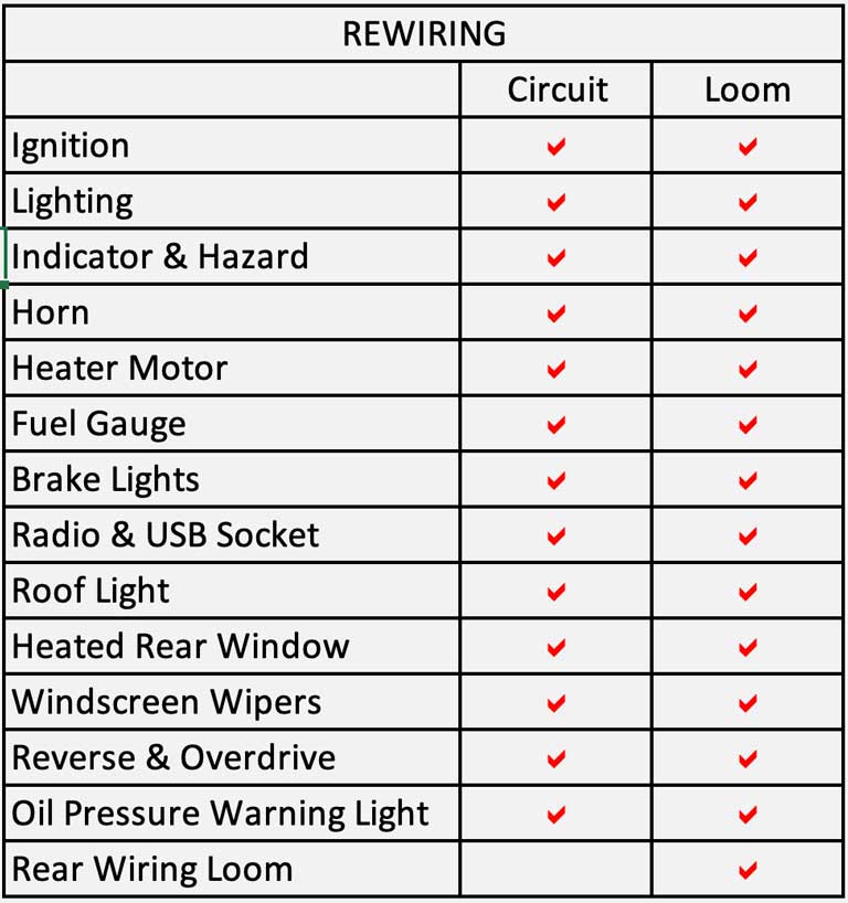
The table below shows the different elements for which first, circuits and ultimately ‘looms’ were designed. For the rear of the car only a ‘loom’ was drawn up.